The QCY T13 has established itself as one of the most cost-effective True Wireless Stereo (TWS) earbuds on the market, offering features like active noise cancellation, Bluetooth 5.1/5.3 connectivity, and proprietary app support at an accessible price point. However, like many budget-to-mid-range audio devices, they are susceptible to charging failures. These issues typically manifest as one earbud refusing to power on, the charging case failing to register an electrical input, or the LED indicators remaining completely dark when connected to a power source.
To fix QCY T13 earbuds not charging, clean the gold-plated pogo pins with 99% isopropyl alcohol and perform a factory hardware reset.
Resolving these charging anomalies requires a systematic diagnostic approach. This article provides an in-depth, engineering-level guide to understanding the electrical architecture of the QCY T13, diagnosing physical and chemical bottlenecks, resetting the onboard microcontroller units (MCUs), and restoring optimal power delivery to both the earbuds and the charging case.
1. Understanding the QCY T13 Electrical Architecture and Charging Mechanism
To effectively troubleshoot the QCY T13, one must first comprehend the electrical pathway that governs its power cycle. The system operates on a dual-stage charging topology consisting of the external power source, the charging case power management integrated circuit (PMIC), and the individual earbud protection circuits.
The charging case houses a 380mAh Lithium-ion (Li-ion) pouch battery with a nominal voltage of 3.7V and a fully charged voltage of 4.2V. When you connect a USB-C cable, the input voltage (typically 5V) passes through an Over-Voltage Protection (OVP) and Over-Current Protection (OCP) integrated circuit. This IC regulates the current entering the battery, employing a Constant Current / Constant Voltage (CC/CV) charging algorithm. During the CC phase, the PMIC supplies a steady current to rapidly elevate the battery voltage to approximately 4.2V. Once this threshold is reached, the system switches to the CV phase, gradually decreasing the current to minimize thermal stress and prevent lithium plating on the anode.
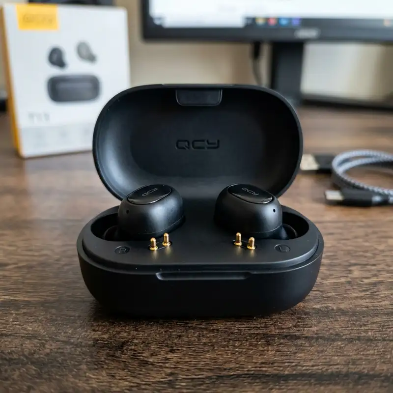
The transfer of energy from the case to the earbuds occurs via a three-point or two-point physical interface using spring-loaded brass pins, commonly referred to as pogo pins. The charging case converts its internal battery voltage up to a regulated 5V boost line to supply power to these pins. Each earbud contains a smaller 45mAh Li-ion battery and its own micro-scale protection board. This onboard board prevents overcharging, over-discharging, and short circuits. If the voltage of either the case battery or the earbud battery drops below a critical threshold (typically 2.4V to 3.0V), the protection IC enters a "sleep" or deep discharge state, cutting off all external current paths until a specific recovery voltage is applied.
2. Diagnosing Contact Resistance and Pogo Pin Oxidation
The most common cause of charging failure in TWS earbuds is contact resistance at the physical interface. The pogo pins in the charging case and the corresponding metal contact pads on the earbuds are typically constructed of brass plated with a thin layer of gold to resist corrosion. However, because these components are in direct contact with human skin, they are constantly exposed to sweat, sebum (skin oils), earwax, and environmental moisture.
Over time, these substances form an insulating chemical barrier over the gold plating. Additionally, galvanic corrosion can occur when electrical current passes through a liquid medium (like sweat) bridging the contacts, accelerating the oxidation of the underlying copper or nickel layers if the gold plating has worn thin. This microscopic buildup increases the contact resistance ($R_{contact}$). According to Ohm's Law ($V = I \times R$), as resistance increases, the voltage drop across the connection increases, and the current flow ($I$) drops. If the charging case PMIC detects that the current draw is below its minimum sensing threshold (often less than 5mA to 10mA), it assumes no earbud is present and shuts off the 5V boost converter to save energy.
To diagnose and resolve this issue, you must perform a meticulous physical restoration of the contacts:
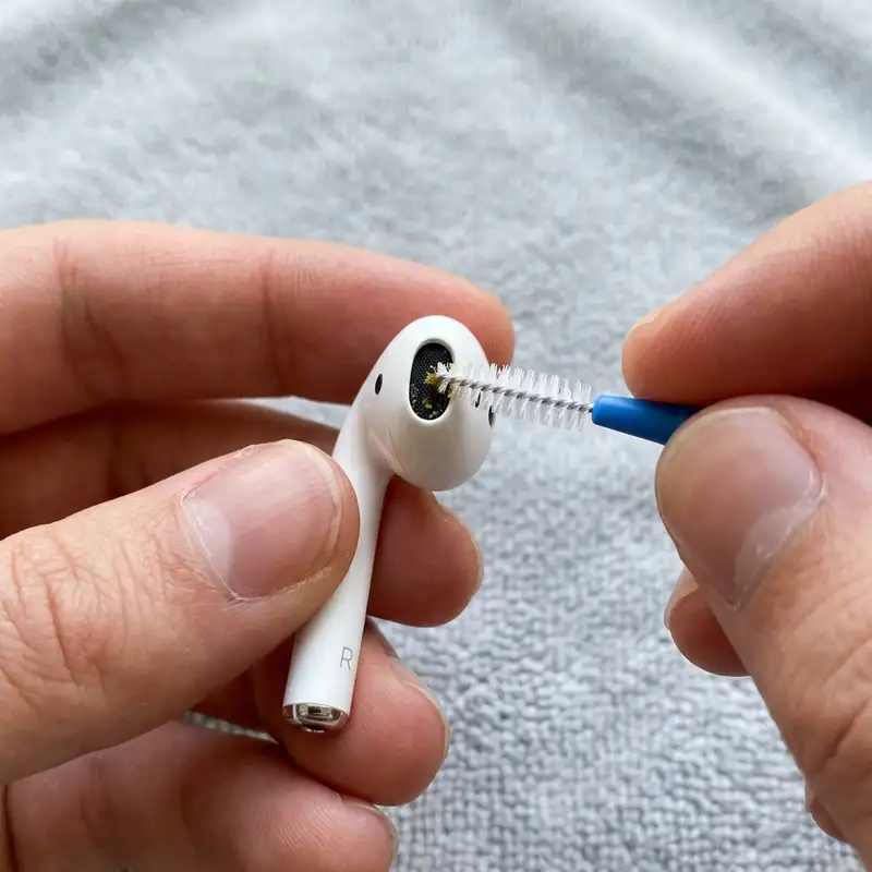
- Chemical Deoxidation: Utilize 99% anhydrous isopropyl alcohol (IPA). Do not use rubbing alcohol containing water, as water can seep into the seam of the earbud housing and cause a short circuit on the PCB. Dip a high-density, lint-free microfiber swab into the IPA and firmly scrub the metal contact pads on the earbuds and the spring-loaded pogo pins inside the case.
- Mechanical Cleaning: If the oxidation is severe (visible as a greenish or dark brown crust), chemical action alone may not suffice. Use the tip of a wooden toothpick or a specialized precision cleaning tool to gently scrape the surface of the contact pads. Avoid using steel pins or sewing needles, as these can scratch off the remaining gold plating, exposing the highly reactive copper underneath to rapid, permanent oxidation.
- Spring Tension Verification: Gently depress the pogo pins inside the charging case using a plastic tool. They should compress smoothly and spring back immediately to their maximum height. If a pin remains stuck in the depressed position, the physical contact pressure ($F_{contact}$) will be insufficient to break through microscopic surface films, resulting in an open circuit. A drop of IPA applied directly to the pin shaft, followed by manual actuation, can often dissolve internal debris and restore spring elasticity.
3. Troubleshooting the Charging Case USB-C Interface and Battery Degradation
If the charging case itself does not show any LED activity when connected to a charger, the failure lies within the USB-C input stage, the internal PMIC, or the Li-ion cell itself. Modern USB-C ports are robust, but they are prone to pocket lint accumulation and structural solder joint failure.
A critical technical detail regarding the QCY T13 is its compliance with the USB Type-C specification. Many budget TWS cases omit the necessary 5.1k ohm pull-down resistors on the Configuration Channel (CC1 and CC2) lines of the USB-C port. When connected to a standard USB-A to USB-C cable (which defaults to a 5V supply), the case charges normally. However, when connected to a smart USB-C to USB-C cable powered by a USB Power Delivery (USB-PD) charger (such as a MacBook or modern smartphone charger), the charger's source controller fails to detect the required pull-down resistance on the CC lines. Consequently, the charger refuses to negotiate a power contract and outputs 0V, leaving the case completely uncharged.
To isolate and resolve these power input anomalies, execute the following steps:
- Downgrade the Power Source: Always attempt to charge the QCY T13 using a standard USB-A to USB-C cable connected to a 5V, 1A or 5V, 2A power brick. Avoid using high-wattage fast chargers that rely strictly on USB-PD or proprietary high-voltage quick-charging protocols.
- Inspect the USB-C Port: Use a high-intensity light source and a magnifying glass to inspect the interior of the USB-C receptacle on the case. Look for compressed lint or debris that may prevent the USB-C cable connector from seating fully. If debris is present, extract it carefully using a non-conductive plastic or wooden probe.
- Assess Internal Battery Voltage: If the case has been left completely discharged for several months, the copper current collectors within the internal Li-ion battery may have dissolved, a chemical process that occurs when the cell voltage drops below 1.5V. When this happens, safety mechanisms inside the battery protection circuit permanently disable the cell to prevent thermal runaway (fire) during subsequent recharge cycles. If the case LED flashes rapidly or does not illuminate even after hours on a 5V/1A charger, the internal pouch battery has reached its end-of-life state and requires replacement or physical servicing.
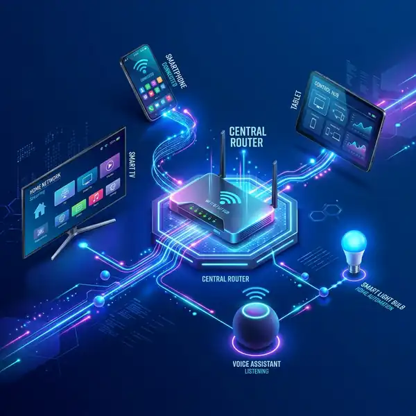
Just as maintaining your digital infrastructure requires precise steps—such as knowing how to reboot router remotely to clear memory leaks—maintaining physical hardware requires strict adherence to electrical specifications and voltage limits.
4. Resolving Firmware and Chipset Lockups (Realtek RTL8753BFE Reset)
Not all charging failures are physical or chemical. The QCY T13 utilizes a highly integrated Bluetooth System-on-Chip (SoC)—typically from the Realtek RTL8753 series or a comparable Jerry/Qualcomm chipset depending on the specific production batch. This SoC handles the RF transceiver, digital signal processor (DSP), power management unit (PMU), and the running firmware stack (handling protocols like A2DP, AVRCP, and codecs such as SBC and AAC modulated via GFSK).
Occasionally, a firmware crash or a corrupt state machine loop can lock the PMU of the earbud. When this occurs, the SoC remains stuck in an active, high-power state, refusing to register that it has been placed into the charging case or failing to transition into the "Power Down / Charging" state. The earbud may continue attempting to connect to the host device via Bluetooth even while inside the closed case, draining its battery to absolute zero. To break this logical lockup, a hardware-level factory reset must be initiated.
Step-by-Step QCY T13 Hardware Reset Protocol:
- Purge Bluetooth Host Cache: On your smartphone, tablet, or PC, open the Bluetooth settings menu. Locate the QCY T13 entry, select "Forget Device" or "Unpair," and temporarily disable Bluetooth on the host device to prevent any automatic reconnection attempts during the reset process.
- Seat the Earbuds: Place both earbuds back into the charging case. Ensure that the LEDs on the earbuds illuminate (even if momentarily) to confirm physical contact with the pogo pins. Keep the charging case lid open.
- Execute the Physical Reset: Locate the physical button situated in the center of the charging case interior. Press and hold this button down continuously for exactly 10 seconds.
- Observe the LED Sequence: During the press, watch the LEDs on both earbuds. They will first pulse or light up continuously. At approximately the 10-second mark, the LEDs will flash red and blue (or red and white, depending on the firmware revision) exactly three times. This visual cue confirms that the non-volatile EEPROM/Flash memory parameters have been cleared, the pairing tables have been wiped, and the SoC's PMU has executed a hard cold boot.
- Power Cycle: Close the charging case lid and connect it to a verified 5V power source for at least 15 minutes to allow the newly reset PMUs to calibrate their battery fuel gauge parameters.
5. Analyzing LED Indicators and Voltage Diagnostics
The QCY T13 uses a simplified LED signaling system to communicate its internal states. Understanding these signals is vital for diagnosing whether the charging failure is localized to the case, the left earbud, the right earbud, or the external power delivery system.
The table below outlines the diagnostic matrix for the QCY T13, correlating LED behavior with physical voltages and target resolution pathways:
| LED Behavior | Component / Location | Estimated Voltage / Current State | System State Diagnosis | Resolution Path |
|---|---|---|---|---|
| Case LED: Solid Red (Plugged In) | Charging Case Battery | Input: 5.0V | Battery: < 3.6V | Case is actively charging in Constant Current (CC) phase. | Allow to charge until LED transitions to green. |
| Case LED: Solid Green (Plugged In) | Charging Case Battery | Input: 5.0V | Battery: 4.15V - 4.25V | Case is fully charged; PMIC has terminated charging cycle. | Disconnect charger; case is ready to supply power to earbuds. |
| Case LED: Rapid Red Flashing | Power Input / USB-C Port | Input: > 5.5V or < 4.5V | Current: 0mA | Over-voltage / under-voltage protection tripped, or thermal limit exceeded. | Switch to a standard 5V/1A charger; cool down the device. |
| Earbud LED: Solid Red (In Case) | Earbud Internal Battery | Pogo Pin: 5.0V | Earbud Battery: < 4.1V | Earbud is drawing current; charging circuit is active. | Normal operation. Allow 1.5 hours for full charge. |
| Earbud LED: Solid Blue/White (In Case) | Earbud Internal Battery | Pogo Pin: 5.0V | Earbud Battery: ~4.2V | Earbud battery is fully charged; protection IC has cut off current. | Normal operation. Earbuds are ready for pairing. |
| Earbud LED: Completely Dark (In Case) | Earbud / Case Interface | Pogo Pin: 0V or < 2.0V | Current: < 1mA | Open circuit due to oxidation, dead case battery, or deep discharge sleep. | Clean contacts, verify case charge, or perform deep discharge recovery. |
If you encounter a "Completely Dark" state on one earbud while the other charges normally, the issue is localized to that specific earbud's physical connection or its internal battery protection board. If the battery has entered a deep discharge state (below 2.4V), the protection IC prevents standard charging currents from entering to protect the cell. To recover a deeply discharged earbud, it must be subjected to a continuous charge cycle inside a fully charged case for a minimum of 4 hours. During this period, the PMIC will slowly apply a micro-current (trickle charge) of less than 1mA to safely rebuild the electrode chemistry until the cell voltage rises above the 3.0V threshold, at which point normal CC/CV charging resumes and the red LED illuminates.
6. Advanced Hardware Solutions: Striking the Battery and Cleaning Internal Corrosion
When standard cleaning, cable swaps, and factory resets fail to restore charging functionality, the issue likely stems from internal physical failures: liquid ingress causing corrosion on the internal PCB, or a chemically locked battery protection IC that cannot be reset via the external interface. These scenarios require advanced hardware intervention.
Addressing Liquid Ingress and Internal Corrosion
Although the QCY T13 features an IPX5 water resistance rating, this protection is designed to withstand sweat and light rain, not submersion or high-pressure water jets. Over time, the adhesive seals around the earbud housing can degrade due to exposure to body heat and sweat. If moisture penetrates the enclosure, it can cause localized short circuits and rapid electrolytic corrosion on the internal PCB traces, particularly around the charging contacts and the battery leads.
To address internal moisture or corrosion:
- Dehumidification: If you suspect recent water exposure, do not place the earbuds in rice (which introduces fine starch dust that can ruin mechanical components). Instead, place the earbuds in a sealed container with several packets of silica gel desiccant for 48 hours.
- Internal Inspection (Advanced): For those comfortable with micro-electronics, the earbud housing can be carefully separated along the factory seam using a thin plastic spudger. Once open, inspect the PCB for white or green powdery residue (copper carbonate). Clean the board using a soft ESD-safe brush and 99% isopropyl alcohol to remove all traces of corrosion. Inspect the solder joints connecting the battery wires to the PCB; cold solder joints or broken wires resulting from drops must be resoldered using a temperature-controlled soldering iron set to approximately 320°C.
"Striking" a Chemically Locked Earbud Battery
When a Lithium-ion battery remains in a discharged state for an extended period, its internal resistance spikes, and the protection circuit board (PCB/PCM) may permanently lock the output terminals to prevent hazardous operation. In professional repair environments, technicians "strike" or jump-start the cell to bypass this lock. This is done by applying a controlled 4.2V current directly to the battery terminals, bypassing the protection IC for a fraction of a second to kick-start the chemical reaction.
While this is an advanced procedure, understanding this concept helps explain why simple USB charger swaps sometimes fail. If you are configuring complex consumer electronics, you might need to troubleshoot software issues, such as learning how to change Wi-Fi password, which relies on a functional logical network. Similarly, hardware debugging requires a functional electrical pathway; if the physical battery cell is chemically locked, no amount of software resetting or external cable swapping will force the QCY T13 PMIC to recognize the earbud.
DomineTec Tip: Press the physical button inside the QCY T13 case with the earbuds inserted to wake up the charging management unit.
Frequently Asked Questions
Why does only one QCY T13 earbud charge while the other remains dead?
This issue is almost always caused by localized contact resistance on the non-charging earbud. Sweat, body oils, or earwax build up on the gold-plated contact pads of that specific earbud or the corresponding pogo pins inside the case, preventing electrical continuity. Clean both contacts thoroughly with 99% isopropyl alcohol. Alternatively, the non-charging earbud may have entered a deep discharge protection state, requiring it to sit in a powered charging case for several hours to slowly rebuild its voltage threshold.
Can I use a fast charger (65W/120W) to charge my QCY T13 case?
It is highly recommended to avoid high-wattage USB-C to USB-C fast chargers. Many budget TWS cases, including the QCY T13, lack the necessary 5.1k ohm pull-down resistors on their CC lines. Consequently, smart USB-PD (Power Delivery) chargers will not output power to the case. Always use a standard USB-A to USB-C cable connected to a basic 5V, 1A or 5V, 2A power adapter to ensure consistent charging and protect the internal PMIC from potential voltage spikes.
Why does the charging case LED blink red rapidly when plugged in?
Rapid red flashing indicates that the charging case's internal safety mechanisms have been tripped. This can occur due to an over-voltage input (using an incompatible high-voltage charger), an under-voltage condition, or thermal protection triggering because the internal Li-ion battery has exceeded safe operating temperatures (typically above 45°C/113°F during charging). Disconnect the charger, allow the case to cool down to room temperature, and reconnect it to a certified 5V/1A power source.
How do I know if the battery in my QCY T13 is permanently dead?
If you have thoroughly cleaned the contacts, verified the functionality of the USB-C cable and charger, performed a complete 10-second hardware reset, and left the earbuds to charge for over 4 hours, yet they still show no LED activity and fail to power on, the internal Li-ion pouch battery has likely suffered permanent copper dissolution or capacity degradation. At this point, the battery has reached its end-of-life cycle and cannot safely hold a charge, requiring replacement of the earbud or the entire unit.
Conclusion
Fixing a QCY T13 charging failure requires a methodical, step-by-step approach that addresses both physical and logical points of failure. By understanding the electrical relationship between the 380mAh case battery and the 45mAh earbud cells, you can systematically eliminate variables. Begin by removing microscopic oxidation from the gold-plated contacts using anhydrous isopropyl alcohol, ensure your charging setup utilizes a compatible USB-A to USB-C configuration to bypass the lack of USB-PD pull-down resistors, and execute a hardware-level EEPROM reset to clear any firmware lockups within the Realtek SoC.
Preventive maintenance is key to extending the operational lifespan of your TWS earbuds. Always dry your earbuds thoroughly before placing them back into the charging case after workouts, avoid exposing the case to extreme thermal environments (such as direct sunlight or inside a hot vehicle), and perform a quick cleaning of the contact pins once a month. This proactive approach minimizes contact resistance, prevents galvanic corrosion, and ensures your QCY T13 earbuds remain fully functional and ready to deliver high-quality audio whenever you need them.